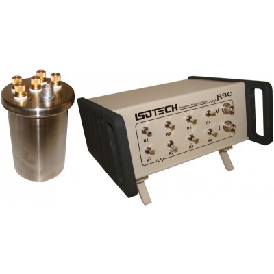
RBC Resistance Bridge Calibrators
Operating principles
The problem: Temperature measurement is one of the most demanding applications of resistance measurement. It requires the measurement of resistance ratios to accuracies of 0.1ppm or better. While dc resistance standards are sometimes available at this level, ac resistance standards are generally not. So how can we show our bridges are accurate at this level, and that our resistance and temperature measurements are traceable?
The linearity check One simple method for checking a resistance bridge is to measure a pair of resistors separately, and then measure the two in series. Ideally the series measurement should equal the sum of the two individual measurements. If not, then the measurements give us a little bit of information about the errors in the bridge readings. Note that we do not need to know the values of the resistors to make this test work.
The combinatorial method The RBC exploits the same principles as the linearity and complement check. It uses a network of four stable fourterminal resistors that can be connected in 35 different series and parallel combinations. By measuring each RBC combination in the two different ways (as with the complement check) up to 70 different measurements can be made. Since the RBC has just four unknown resistance values, we have up to 66 independent measurements containing information about the errors in the bridge readings. The combinatorial calibration method is particularly powerful because it is not necessary to know the actual values of the four resistors, or their frequency dependence. This means we can calibrate any ac or dc bridge to any accuracy, so long as the various resistance combinations are accurate.
The patented RBC Calibrators are a result of research carried out by Rod White at the Measurement Standards Laboratory of New Zealand, which operates within Industrial Research Ltd (IRL). Isothermal Technology Ltd has an exclusive license from IRL to develop, sell and produce the RBC.
The linearity check One simple method for checking a resistance bridge is to measure a pair of resistors separately, and then measure the two in series. Ideally the series measurement should equal the sum of the two individual measurements. If not, then the measurements give us a little bit of information about the errors in the bridge readings. Note that we do not need to know the values of the resistors to make this test work.
The complement check
Another check is to measure the ratio of two resistances, say R1/R2, then swap the resistors and measure the reciprocal ratio (or complement), R2/R1. Ideally the product of the two measurements should equal 1.0 exactly, if not, the measurements give us more information on the bridge errors. Once again, we do not need to know the values of the resistors to make this test work.
The combinatorial method The RBC exploits the same principles as the linearity and complement check. It uses a network of four stable fourterminal resistors that can be connected in 35 different series and parallel combinations. By measuring each RBC combination in the two different ways (as with the complement check) up to 70 different measurements can be made. Since the RBC has just four unknown resistance values, we have up to 66 independent measurements containing information about the errors in the bridge readings. The combinatorial calibration method is particularly powerful because it is not necessary to know the actual values of the four resistors, or their frequency dependence. This means we can calibrate any ac or dc bridge to any accuracy, so long as the various resistance combinations are accurate.
The patented RBC Calibrators are a result of research carried out by Rod White at the Measurement Standards Laboratory of New Zealand, which operates within Industrial Research Ltd (IRL). Isothermal Technology Ltd has an exclusive license from IRL to develop, sell and produce the RBC.
| Manual Specification |
Automatic Specification | |
|---|---|---|
| Accuracy | <0.1ppm at 100Ω (For DC and AC to 400 Hz) | <0.01ppm at 100Ω (For DC and AC to 400 Hz. When RBC is temperature controlled). |
| Temperature coefficient | < ±0.3 ppm/ °C | < ±0.3 ppm/ °C |
| Maximum Sensing Current | RBC100M - 10mA, RBC400M - 5mA. | RBC100A - 5mA, RBC400A - 3mA |
| Resistance Range | RBC100M: 16Ω to 127Ω, RBC400M: 43Ω to 346Ω | RBC100A - 5mA, RBC400A - 3mA |
| Power Supply | None - the RBC is completely passive | 5V, via the USB cable. Idle current typically less than 5mA, switching currents less than 200mA. |
| Connections | Four-terminal coaxing using separate BNC for the current and voltage leads | Signal: five-terminal guarded dc spade lugs |
| Case Dimensions | Width: 215mm, Height: 105mm, Depth 200mm. (2U height by half rack width) | Diamter 88mm, Height 140mm, Identical to Tinsley type standard resistors. |
| Digital Control | - | USB |
| Weight | 2.5kg | 1.25kg |
| Software | Tabular and graphical representation of data Least-squares fit to determine model of bridge error Tabular summary of data and results. Print calibration report. | Tabular and graphical representation of data Least-squares fit to determine model of bridge error Tabular summary of data and results. Print calibration report. |
| Minimal Hardware Requirements | 486/66 PC. 8Mb RAM (16 Mb for NT), SVGA (800 X 600) monitor, Compatible with Microsoft Windows Platforms | 486/66 PC. 8Mb RAM (16 Mb for NT), SVGA (800 X 600) monitor, Compatible with Microsoft Windows Platforms |

