OM 21
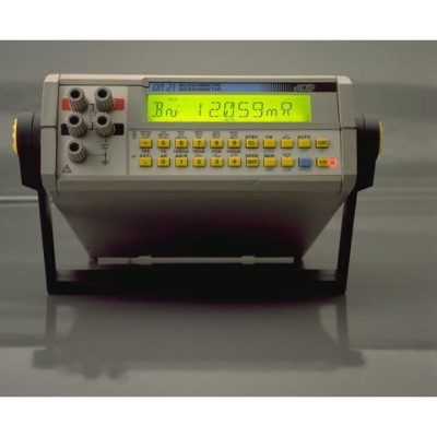
OM 21 benchtop micro-ohmmeter is used for 4-wire measurement of very low resistance values up to 20 kΩ with an accuracy of 0.03% RDG and a 0.1 µΩ resolution. The reliability and accuracy of the measurements is improved by a low temperature coefficient of 10 ppm/°C, automatic removal of EMF parasites before each measurement, metal temperature compensation and compensation of ambient temperature.
With three current waveforms available -continuous, pulse or AC current- from 100 µA to 10 A and high flexibility of trigger and sampling conditions, OM 21 low resistance ohmmeter covers a wide range of applications: Cable resistance and resistivity measurement, inductive resistance measurement (motors and transformers winding resistance),contact resistance measurement (connectors, switches, relays…),test of low power electrical components (fuses…) and heat sensitive devices, metallisation / earth bonding and ground continuity measurement.
OM 21 is fully programmed by the user, either directly through the instrument interface or through LOG OM data management software delivered in option: choice of measuring current, resistance range, measuring unit, metal under test, alarms, triggering conditions, storage of measurement.
Up to 1,000 samples can be stored inside the instrument and be recalled directly on the display or on computer via LOG OM.Powered from mains or from rechargeable batteries, the electronic calibration of the instrument is performed without any internal adjustment.
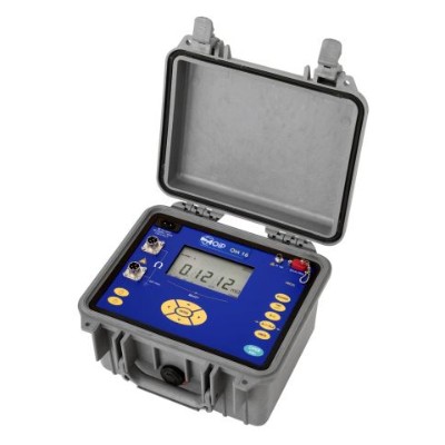
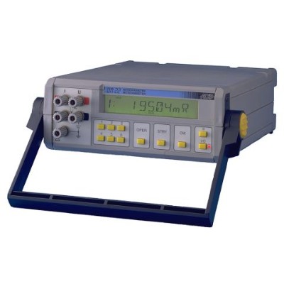
For use on test benches, you might want to consider OM 22 micro-ohmmeter instead of OM 21. It has the exact same specifications of OM 21 but is more adapted to repetitive measurement tasks. While OM 21 can be either manually or automatically operated and is fully programmable by the user through the instrument interface, OM 22 has 6 set configurations inside to be selected by the user. More information over OM 22 here.
| Range | Resolution | Accuracy at 90 days(23°C ±1°C) | Measuring current | Voltage drop |
|---|---|---|---|---|
| 2 mΩ | 0.1 μΩ | 0.05% + 0.3 μΩ | 10 A | 20 mV |
| 20 mΩ | 1 μΩ | 0.05% + 2 μΩ | 10 A | 200 mV |
| 20 mΩ | 1 μΩ | 0.05% + 3 μΩ | 1 A | 20 mV |
| 200 mΩ | 10 μΩ | 0.05% + 10 μΩ | 10 A | 2 V |
| 200 mΩ | 10 μΩ | 0.05% + 20 μΩ | 1 A | 200 mV |
| 200 mΩ | 10 μΩ | 0.05% + 30 μΩ | 100 mA | 20 mV |
| 2 Ω | 100 μΩ | 0.05% + 100 μΩ | 1 A | 2 V |
| 2 Ω | 100 μΩ | 0.03% + 200 μΩ | 100 mA | 200 mV |
| 2 Ω | 100 μΩ | 0.03% + 300 μΩ | 10 mA | 20 mV |
| 20 Ω | 1 mΩ | 0.03% + 1 mΩ | 100 mA | 2 V |
| 20 Ω | 1 mΩ | 0.03% + 2 mΩ | 10 mA | 200 mV |
| 20 Ω | 1 mΩ | 0.03% + 3 mΩ | 1 mA | 20 mV |
| 200 Ω | 10 mΩ | 0.03% + 10 mΩ | 10 mA | 2 V |
| 200 Ω | 10 mΩ | 0.03% + 20 mΩ | 1 mA | 200 mV |
| 200 Ω | 10 mΩ | 0.03% + 30 mΩ | 100 µA | 20 mV |
| 2 kΩ | 100 mΩ | 0.03% + 100 mΩ | 1 mA | 2 V |
| 2 kΩ | 100 mΩ | 0.03% + 200 mΩ | 100 µA | 200 mV |
| 20 kΩ | 1 Ω | 0.03% + 1 Ω | 100 µA | 2 V |
Further features
| Resistance types | Inductive resistances: Coils, transformers, motor windings...Non-inductive resistances: Earth bonding, coating, contact resistances... |
|---|---|
| Measuring current | Internal or external sourceDC current from 100 µA to 10 AContinuous, pulsed or pulsed alternated |
| Measurement time | < 1 s in direct current mode< 1,5 s in pulse current mode< 2 s in alternate current mode |
| Measurement trigger conditions | Manual or automatic trigger from 2 measures/s to 1 measure/9h, allowing a single operator to be able to perform measurements |
| EMFs | Automatic compensation of EMF parasites before each measurement for a greater accuracy |
| Temperature compensation | Choice of metal temperature coefficientChoice of ambient temperature (programmed or measured with external probe)Temperature compensation at 20°C: Resolution: 0.1°C, accuracy: ±0.5°C(R20 = Resistance compensated at ambient temperature equal to 20°C |
| Temperature coefficient beyond operating range | < 10% accuracy/°C |
| Relative measurements | Display L = R-R0 or L = 100 x (R-R0)/R0 in %Where L: read value, R: measured value and R: reference value either recalled from memory or entered by the operator |
| Coil heating calculation | Coil heating calculation according to ambient temperature, original coil resistance at ambient temperature, coil resistance once heated and coil material |
| Alarms | 2 programmable thresholds with visual and sound signal and relay outputs |
| Outputs | Two relays (1 A / 220 VAC)1 analogue output 0 – 2.5 V (load >= 2.5 kΩ, resolution: 10 mV, accuracy: ±10 mV) |
| Calibration | Digital calibration without internal adjustment |
General specifications
| Size | 225 x 88 x 310 mm |
|---|---|
| Weight | 2 to 3 kg depending on options |
| Display | LCD 26,000 counts, 16 figures lighted, 11.5 mm high |
| Power supply | 115 / 230 V (50 / 60 Hz) |
| Battery with internal charger(option) | Type: 12 V battery packBattery life:2 to 8 h according to useCharging time: 14 h |
| Communication ports | RS 232 in standardIEEE 488-2 in optionAllows programming, data management and unit calibration directly from a computer |
| Storage capacity | 1,000 measurements with average, minimum and maximum valueMemory reading directly on the display or through digital and analogue interfaces |
Environmental specifications
| Reference range | 23°C ±1°C (RH: 45 to 75 % w/o condensing) |
|---|---|
| Operating reference range | 0 to 50°C (RH: 20 to 80 % w/o condensing) |
| Limit operating range | -10°C to +50°C (RH: 10 to 80 % w/o condensing) |
| Storage temperature limits | -30°C to +55°C(- 15°C to + 50°C for model with battery) |
| Protection IP | IP40 according to EN60529 |
| Maximum altitude | 2,500 m |
Safety specifications
| Protections | Electronic protection for ‘voltage’ wiresFuse protection for ‘current’ wiresProtection against ‘current’ circuit breaking during inductive resistance measurements |
|---|---|
| Class | In accordance with EN 61010-1Category III, pollution 2 |
| Rated voltage | 50 V |
| Chocks and vibrations | EN61010-1 |
| EMC conformity | Immunity:EN 50082-1/1992Conducted and radiated emissions:EN 55022, class BRadiated: IEC 801-3/1984Conducted: IEC 801-4/1988Electrostatic discharges: IEC 801-2/1991 |


